Difference between revisions of "Particle image velocimetry (PIV)"
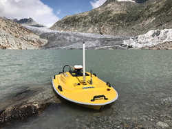
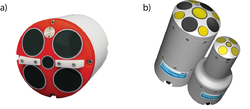
Bendikhansen (talk | contribs) (Created page with "=Quick summary= file:adcp_example_units.png|thumb|250px|Figure 1: Exemples of ADCPs: (a) Teledyne RiverPro with 5 beams (source: http://www.teledynemarine.com) and (b) Sonte...") |
Bendikhansen (talk | contribs) |
||
| Line 44: | Line 44: | ||
=Application= | =Application= | ||
| − | + | For the application, the study area needs to be well known and targets need to be distributed in the area to ensure a defined distance for calibration on the pictures. As due to the huge amount of seeding needed for one run, not too many tests can be run and it is highly recommended to prepare the experiment properly. | |
| − | + | *Set up of targets (either own targets such as wooden crosses or coded targets can be used). The coded targets are especially of interest in case the measurement shall be combined with a Structure from Motion measurement | |
| + | *Preparation of the drone, best case would be an automated flight route, however, also manual flights are possible without any problem | ||
| + | *Preparation of any other measurement devices to be used at the same time, when the seeding starts floating everything needs to run smoothly | ||
| + | *Preparation of the team which is responsible for spreading the seeding: based on a detailed planning it needs to be ensured, that the seeding is present in a sufficient amount under the drone, hence visible in the picture taken. | ||
| + | *In general, it depends on the camera of the resolution and frequency for pictures or movies is better | ||
| + | *A second run of the experiment would be recommended | ||
| − | + | After the data collection in the field, the more time consuming part is the data evaluation. Therefore different software can be used. Usually all variations of commercial products such as the PIV software of DanTec, ILA or LaVision. Further free software such as PIVlab can be used. | |
| − | |||
| − | |||
| − | |||
| − | |||
| + | Depending on the software different levels of own effort are necessary when it comes to rectification of the pictures (Detert et al. 2015; Patalano et al 2017). The software is, when using PIVlab, MATLAB based and the basic idea is the same as for a standard PIV. | ||
=Other information= | =Other information= | ||
Revision as of 09:16, 19 June 2019
Contents
Quick summary
Developed by: Various Companies
Date:
Suitable for the following [[::Category:Measures|measures]]:
Introduction
Particle Image Velocimetry (PIV)
The particle image velocimetry (PIV), is an optical technique to measure the velocity of a fluid by measuring the velocity of the movement of particles transported in this fluid assuming that the particles are transported with the fluid without losses or disturbances.
The main devices used for this technique are:
- A source of light (for PIV usually a laser, however strong LED lights become more popular)
- At least one camera (in case of a 3D or volume measurement up to at least 4 cameras)
- Synchronizer to be able to automatically synchronize the camera (times when the pictures are taken) with the laser, otherwise, the pictures would not be properly illuminated
- Software for evaluation of the results
- Mostly also tracer particles as seeding
PIV is an instantaneous method to measure the flow. The main set-up includes usually a laser as a source of light (see Figure 63). With this laser, a so called laser sheet, a plain area within the fluid which is enlightened with the laser is created. All particles transported with the fluid are supposed to reflect the light and become visible like that. This effect can be supported by the use of special tracer particles (which are quite costly, so this is only recommended for lab use).
A camera takes pictures of the moving particles in predefined very short time intervals t. Based on the known t the flow velocity can be calculated using special algorithms to evaluate the movement of the seeding points visible in the picture. The evaluation of the pictures uses an Eulerian’ approach. To be able to evaluate the distances on the pictures the system needs to be calibrated. As both, the time between the two pictures as well as the distance one particle has moved comparing these pictures the particle and hence the fluid velocity can be calculated.
To be able to achieve good results it is necessary to mind certain rules such as that one particle on the resulting picture should have the size of approx.. 2-3 pixel etc. It is highly recommended to get a detailed view into the literature (i.a. Raffel et al 2007) before starting with a measurement.
The PIV can be bought as a complete system, usually including the software. Different companies such as ILA Laser applications, Dantec or LaVision offer this possibility including support. Some research institutions and universities also develop their own codes for post-processing depending on their needs or build the laser or camera system on their own.
Large Scale PIV (LS-PIV) or Airborne Image Velocimetry (AIV)
Based on the idea of PIV the so called Large Scale PIV (LS-PIV) or Airborne Image Velocimetry (AIV) was developed. As “Large Scale” with the increasing technical possibilities became a quite wide meaning the term AIV is more correct nowadays and used hereinafter.
The measurement and evaluation technique is basically the same set-up and underlying theory as PIV and adapts this for use on large scale mainly in the field. As mentioned above the term large scale is not defined, generally, it means more than lab size with about max. 1.5m x 1.5m for very good conditions. Such as a PIV the AIV is an optical system used to measure flow velocities, other than the PIV mainly surface velocities in 2D.
Instead of Laser as a source of light, the AIV uses the sun. This might become a problem for the evaluation of the pictures when direct sun is present, as reflections will affect the quality of the results.
The camera is often mounted on a UAV to ensure a sufficient size of the pictures taken as a result of greater distance and angle (Figure 64). Seeding is recommended for a sufficient quality of results. As the seeding, other than for the use with PIV, is used in a natural environment and most likely it will not be possible to collect it back behind the area of interest it is necessary to use seeding which is biodegradable such as wood chips or maize flips (packing material). Any other material which is biodegradable and available can be used as well as long as it is following the flow and is visible on the pictures taken.
Application
For the application, the study area needs to be well known and targets need to be distributed in the area to ensure a defined distance for calibration on the pictures. As due to the huge amount of seeding needed for one run, not too many tests can be run and it is highly recommended to prepare the experiment properly.
- Set up of targets (either own targets such as wooden crosses or coded targets can be used). The coded targets are especially of interest in case the measurement shall be combined with a Structure from Motion measurement
- Preparation of the drone, best case would be an automated flight route, however, also manual flights are possible without any problem
- Preparation of any other measurement devices to be used at the same time, when the seeding starts floating everything needs to run smoothly
- Preparation of the team which is responsible for spreading the seeding: based on a detailed planning it needs to be ensured, that the seeding is present in a sufficient amount under the drone, hence visible in the picture taken.
- In general, it depends on the camera of the resolution and frequency for pictures or movies is better
- A second run of the experiment would be recommended
After the data collection in the field, the more time consuming part is the data evaluation. Therefore different software can be used. Usually all variations of commercial products such as the PIV software of DanTec, ILA or LaVision. Further free software such as PIVlab can be used.
Depending on the software different levels of own effort are necessary when it comes to rectification of the pictures (Detert et al. 2015; Patalano et al 2017). The software is, when using PIVlab, MATLAB based and the basic idea is the same as for a standard PIV.
Other information
The total costs for the geophone and accelerometer sensors amount to approx. 885-1'330 €. The costs for the field computer, the analog-digital-converter, and the 3G modem are approx. 5'300-6'200 €. The total costs for the Teledyne RiverPro 1200 kHz, Teledyne Q-boat and DGPS from Hemisphere Atlas link amount to approx. 22’000 €, 21’200 € and 3’340 € respectively. The costs of shipping, VAT, some mounting apparatus and long-range radio modem are excluded. For current costs of the equipment, we recommend to ask the corresponding supplier. Note that Q-boat can also house Sontek RiverSurveyor M9. Furthermore, a rugged laptop for field use is recommended.
Relevant literature
- Mueller, D.S., Wagner, C.R., Rehmel, M.S., Oberg, K.A., Rainville, F. (2013). Measuring discharge with acoustic Doppler current profilers from a moving boat (ver. 2.0, December 2013), U.S. Geological Survey Techniques and Methods, book 3, chap. http://dx.doi.org/10.3133/tm3A22.
- Simpson, M.R. (2002). Discharge measurements using a broadband acoustic Doppler current profiler. Open-file Report 2001-1, https://doi.org/10.3133/ofr011.
Links to the suppliers of equipment:
- Teledyne Marine, ADCP RiverPro: http://www.teledynemarine.com/riverpro-adcp?ProductLineID=13
- Teledyne Marine, Q-Boat: http://www.teledynemarine.com/Lists/Downloads/Q-Boat_1800_Datasheet.pdf
- Hemisphere Atlas DPS: https://hemispheregnss.com/Atlas/atlaslinke284a2-gnss-smart-antenna-1226
- Sontek ADCP M9: https://www.sontek.com/riversurveyor-s5-m9
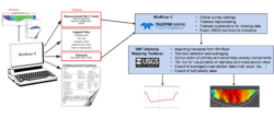
Software for ADCP data analysis:
- Velocity Mapping Toolbox: https://hydroacoustics.usgs.gov/movingboat/VMT/VMT.shtml
- Q-GIS: https://qgis.org/en/site/
