Current meter
Contents
Quick summary
Developed by: Various Companies
Date:
Type: Device
Suitable for the following [[::Category:Measures|measures]]:
Introduction
The first devices to measure flow velocities appeared during the 1780s with the first mechanical current meter which counts the rotations of a propeller and links it to the flow velocity (by proportionality principle).
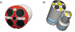
Today there are 3 different techniques to assess the flow velocity: mechanically, electromagnetically, and acoustically (Figure 73). The acoustic current meters using the Doppler Effect are not presented here, as these tools (ADCP, ADV, etc.) are presented separately.
Application
For a mechanical flow meter, the rotation of the propeller produces an electrical impulse detected and recorded by a counter connected to the current meter. The electromagnetic flow meter uses the Faraday law. The sensor creates a magnetic field between two electrodes located at the end of the probe. The flow velocity is deduced from the measurement of the electromagnetic force generated by the passage of water through the magnetic field.
The measurement conditions of discharge through flow velocity fields are regulated by the European standard NF EN ISO 748. The velocities are measured along a cross section at verticals. The number of verticals (n) depends on the width of the channel:
- Width of channel < 0,5 m, n = 5 or 6
- Width of channel > 0,5 m and < 1 m, n = 6 or 7
- Width of channel > 1 m and < 3 m, n = 7 or 12
- Width of channel > 3 m and < 5 m, n = 13 to 16
- Width of channel > 5 m, n ≥ 22
One method among others to measure the mean velocity on each vertical is to measure the velocity in one or several measurement points at different water levels on the vertical. The number of measurements points for each vertical depends on the water level. For example, only one point is needed for water level <20 cm at 60% of the water level. If there are only 2 measurement points, they should be at 20 and 80% of the water level, and the mean velocity corresponds to the average of the two measured velocities. In the following example, 6 measurements were selected (Figure 74). The example is linked to the velocity profile inside a downstream migration channel, which is not logarithmic.
Other information
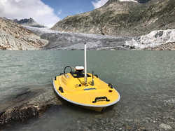
The total costs for the geophone and accelerometer sensors amount to approx. 885-1'330 €. The costs for the field computer, the analog-digital-converter, and the 3G modem are approx. 5'300-6'200 €. The total costs for the Teledyne RiverPro 1200 kHz, Teledyne Q-boat and DGPS from Hemisphere Atlas link amount to approx. 22’000 €, 21’200 € and 3’340 € respectively. The costs of shipping, VAT, some mounting apparatus and long-range radio modem are excluded. For current costs of the equipment, we recommend to ask the corresponding supplier. Note that Q-boat can also house Sontek RiverSurveyor M9. Furthermore, a rugged laptop for field use is recommended.
Relevant literature
- Mueller, D.S., Wagner, C.R., Rehmel, M.S., Oberg, K.A., Rainville, F. (2013). Measuring discharge with acoustic Doppler current profilers from a moving boat (ver. 2.0, December 2013), U.S. Geological Survey Techniques and Methods, book 3, chap. http://dx.doi.org/10.3133/tm3A22.
- Simpson, M.R. (2002). Discharge measurements using a broadband acoustic Doppler current profiler. Open-file Report 2001-1, https://doi.org/10.3133/ofr011.
Links to the suppliers of equipment:
- Teledyne Marine, ADCP RiverPro: http://www.teledynemarine.com/riverpro-adcp?ProductLineID=13
- Teledyne Marine, Q-Boat: http://www.teledynemarine.com/Lists/Downloads/Q-Boat_1800_Datasheet.pdf
- Hemisphere Atlas DPS: https://hemispheregnss.com/Atlas/atlaslinke284a2-gnss-smart-antenna-1226
- Sontek ADCP M9: https://www.sontek.com/riversurveyor-s5-m9
Software for ADCP data analysis:
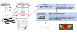
- Velocity Mapping Toolbox: https://hydroacoustics.usgs.gov/movingboat/VMT/VMT.shtml
- Q-GIS: https://qgis.org/en/site/
