Vertical slot fishways
Contents
Introduction
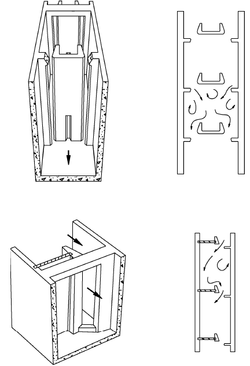
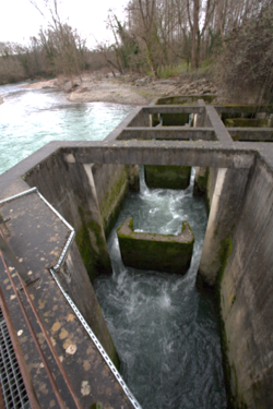
This type of fishway was developed in North America (Clay, 1961), following several studies on models. The pools may have one or two deep slots (Figure 1), depending on the size of the watercourse and the discharge available. The advantage of having two slots is to be able to increase the flow in the device, instead of an attraction flow injection system or to compensate a moderate head drop at the entrance.
The geometry of cross-walls with deflectors has been the subject of a number of studies ( (Rajaratnam, et al., 1986), (Lenne, 1990), (Larinier, et al., 2002), (Romao, et al., 2017)) and, from the compilation of geometrics characteristics of about thirty vertical slot fishways built in France (Wang, et al., 2010), the dimensions of a typical cross-wall can be proposed (Figure 2):
The flow from the slot is oriented and tends to be directed to the middle of the pool at an angle of 30-45°, resulting in efficient energy dissipation in all the water volume of the pool. When there are two slots, the flow converges and meets in the central section of the pool, creating calm zones on each side of the pool immediately downstream from the walls.
Hydraulic organization of the flows in the pools has also been the subject of numerous studies ( (Rajaratnam, et al., 1986) (Lenne, 1990) (Rajaratnam, et al., 1992), (Wu, et al., 1999), (Puertas, et al., 2004) (Liu, et al., 2006)). Criteria are recently given to obtain a proper organization of the flows in the pools (Wang, et al., 2010). The pool’s length L is generally 7 to 12 times the width of the slot b. For a basin length of 10 b and a fishway slope of 5%-7.5%, a pool’s width B equal to 7-7.5 b could be adopted so as to obtain a two-recirculation zone flow topology and avoid the jet impacting the side opposite the slot. The study of fish behavior (trout and chub) in a ¼ scale vertical slot fishway model, testing different pool width B on slot width b ratios, showed a better rate of fish passage for the two-recirculation zone flow topology than a unique recirculation zone flow topology (obtained when B/b <7). For different pool lengths, one can recommend keeping the same width / length ratio (0.7-0.75). In case of double-slots fishway, the pool width is usually 9 to 10 times b (Larinier, et al., 2002).
A sill can be installed at the base of the slot, especially to limit flow in the device. Sill forces the orientation of the jet to the side opposite the slot, with the hydraulic consequences of reducing the flow topology to one recirculation zone. Moreover, the flows immediately downstream from the sill will tend to plunge (Ballu, et al., 2015).This flow pattern appears less favorable for fishes, after testing with trout on a ¼ scale model (Ballu, 2017). As far as possible, taking into account these experiments, we recommend not installing any sill in the slot.
The flow through a vertical slot fishway can be expressed by the formula:
Where:
- = flow discharge (m3/s)
and
- = width of the slot (m)
- = head at the slot (m), i.e. the difference between the water level upstream of the slot and that of the slot crest
- = acceleration due to gravity (9.81 m/s2)
- = drop between the two pools (m)
- = discharge coefficient of the slot
The coefficient of discharge is dependent on the slot configuration/layout ( (Bombac, et al., 2017; Romao, et al., 2017)), width and the water depth ( (Rajaratnam, et al., 1986) (Wu, et al., 1999), (Fuentes-Pérez, et al., 2014)), the design of the baffle and the global geometry of the pools (Puertas, et al., 2004), the slope (Wang, et al., 2010) or even the presence of sill in slot (Ballu, et al., 2015) or roughness on the bottom of the pool (Ballu, et al., 2017)). In general, it may vary from 0.65 to 0.85, depending of the configuration of these parameters.
The great advantage of the vertical slot fishway is that it can accommodate significant variations in the upstream water level, provided that the level downstream is subjected to similar variations. The conditions of velocity and turbulence remain very stable, whatever the water levels in the fishway, and fish can pass through the fishway, swimming at its preferred depth
Methods, tools, and devices
During planning
Planning of a vertical slot fishway will start with mapping and surveying of the barrier itself and the river reach upstream and downstream of the barrier, including information about the hydropower scheme. Surveying must also be conducted in the area of the river bank where the fishway is planned, including geological surveying. Geographic data should be handled in GIS software for further planning and analyses. The design of the fishway should be conducted with conventional hydraulic and civil engineering calculations and drawing (see FIThydro deliverable 2.1). All material used in a fishway must be planned to withstand physical strain from water, floods and frost. Monitoring facilities should basically be planned in the upper part of the fishway.
During implementation
Physical implementation of vertical slot fishways requires heavy machinery suited for the river size and its surrounding terrain, such as excavators and trucks. Work with explosives is relevant in most cases and blasted rocks and transportation of material out from the site is common. Surplus rocks should not be disposed at site because of pollution risk. The construction phase includes construction of concrete formwork, casting of concrete and iron reinforcement work.
During operation
Injuries on vertical slot fishways from physical wear must be monitored and repaired in order to secure regular fish migration. Maintenance work normally require hand-tools more than heavy equipment, but casting of concrete is typical. Depending of the site, removal of sediment, branches, logs and floating debris in pools and fishway entrance is common. Monitoring systems require regular inspection, depending on product and system.
Relevant MTDs and test cases
Classification table
| Classification | Selection |
|---|---|
| Fish species for the measure | 0 |
| Does the measure require loss of power production | Operational (requires flow release outside turbine) |
| - | |
| - | |
| Recurrence of maintenance | Irregular at events |
| Which life-stage of fish is measure aimed at | - |
| - | |
| - | |
| Movements of migration of fish | |
| Which physical parameter is addressed | N/A |
| - | |
| - | |
| - | |
| - | |
| - | |
| - | |
| - | |
| Hydropower type the measure is suitable for | Plant in dam |
| Plant with bypass section | |
| Dam height (m) the measure is suitable for | Up to 10 |
| Section in the regulated system measure is designed for | In dam/power plant |
| - | |
| - | |
| - | |
| River type implemented | Steep gradient (up to 0.4 %) |
| Fairly steep with rocks, boulders (from 0.4 to 0.05 %) | |
| Slow flowing, lowland, sandy (less than 0.05 %) | |
| Level of certainty in effect | Very certain |
| Technology readiness level | TRL 9: actual system proven in operational environment |
| Cost of solution | See cost table |
Relevant literature
- Ballu, A. 2017. Etude numérique et expérimentale de l'écoulement turbulent au sein des passes à poissons à fentes verticales. Analyse de l'écoulement tridimensionnel et instationnaire. s.l. : Thèse de doctorat - Université de Poitiers, 2017.
- Ballu, A., et al. 2017. Experimental study of the influence of macro-roughnesses on vertical slot fishway flows. La Houille Blanche. May 2017, 2, pp. 9-14.
- Ballu, A., et al. 2015. Experimental study of the influence of sills on vertical slot fishway flow. The Hague - The Netherlands : Proceedings of the 36th IAHR World Congress, 2015.
- Bombac, M., Cetina, M. et Novak, G. 2017. Study on flow characteristics in vertical slot fishways regarding slot layout optimization. Ecological Engineering. 107 : 126-136, 2017.
- Clay, H. C. 1961. Design of fishways and other fish facilities. s.l. : Department of Fisheries of Canada, p. 301.
- Fuentes-Pérez, JF., et al. 2014. Modeling water-depth distribution in vertical slot fishways under uniform an non-uniform scenarios. Journal of Hydraulic Engineering, 140, 6014016. 2014.
- Larinier, M., Travade, F. et Porcher, J. P. 2002. Fishways: biological basis, design criteria and monitoring. 2002, p. 208.
- Lenne, D. 1990. Circulation des poissons migrateurs : franchissement des buses et étude hydraulique des passes à bassins successifs. s.l. : EN1TRS CEMAGREF, 70 p.
- Liu, M., Rajaratnam, N. et Zhu, D.Z. 2006. Mean flow and turbulence structure in vertical slot fishways. Journal of hydraulic engineering, 10.1061. 2006.
- Puertas, J., Pena, L. et Teijeiro, T. 2004. Experimental approach to the hydraulics of vertical slot fishways. Journal of Hydraulic Engineering, 130. 2004, pp. 10-23.
- Rajaratnam, N., Van der Vinne, G. et Katopodis, G. 1986. Hydraulics of vertical slot fishways. Journal of Hydraulic Engineering. 1986, Vol. 112, 10, pp. 909-927.
- Rajaratnam, N., Katapodis, C. et Solanki, S. 1992. New designs for vertical slot fishways. 1992, pp. 402-414.
- Romao, F., et al. 2017. Passage performance of two cyprinids with different ecological traits in a fishway with distinct vertical slot configurations. Ecological Engineering. 105 : 180-188, 2017.
- Wang, R.W., David, L. et Larinier, M. 2010. Contribution of experimental fluid mechanics to the design of vertical slot fish passes. Knowledge and Management of Aquatic Ecosystems. 2010, pp. 366, 02
- Wu, S., Rajaratnam, N. et Katapodis, C. 1999. Structure of flow in vertical slot fishway. Journal of Hydraulic Engineering 125 (4). 1999, pp. 351-360.


